

Products Description
| Company Information | |||
| [email protected] | |||
| Mobile | +8613950166376 | ||
| +8613950166376 | |||
| 13950166376 |
Technical Specifications
|
Parameter |
Specification |
|---|---|
|
Manufacturer |
Allen-Bradley |
|
Model |
|
|
Product Type |
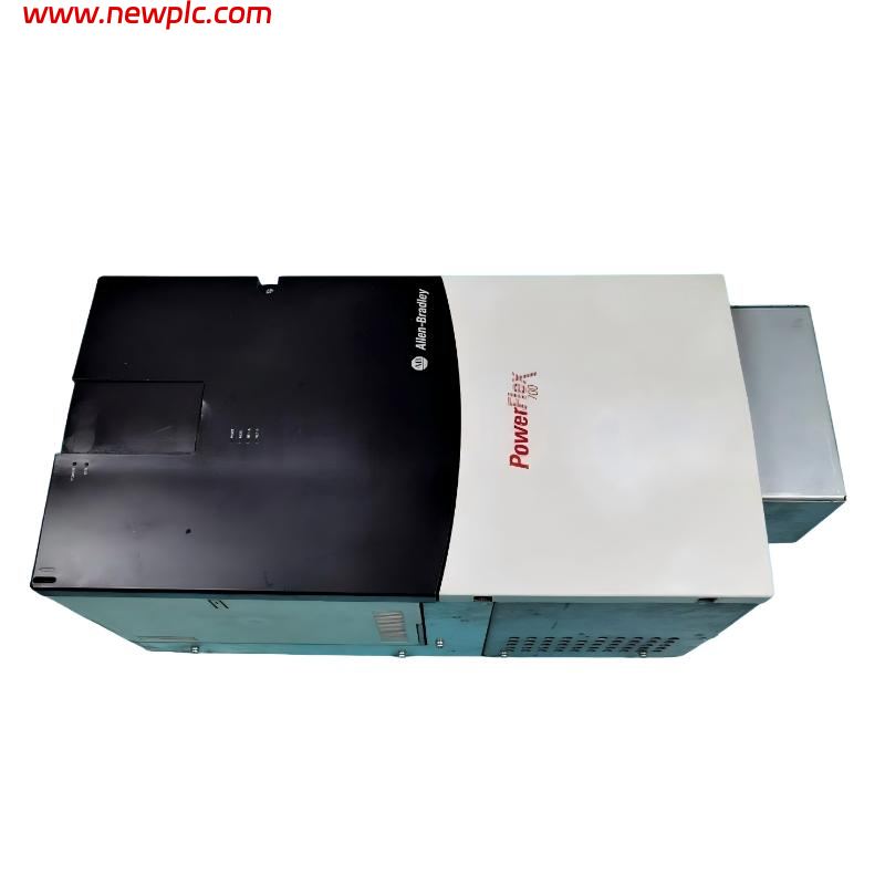
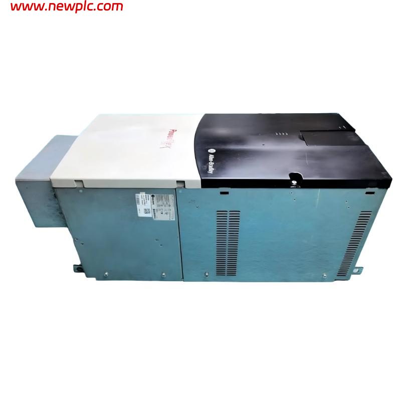
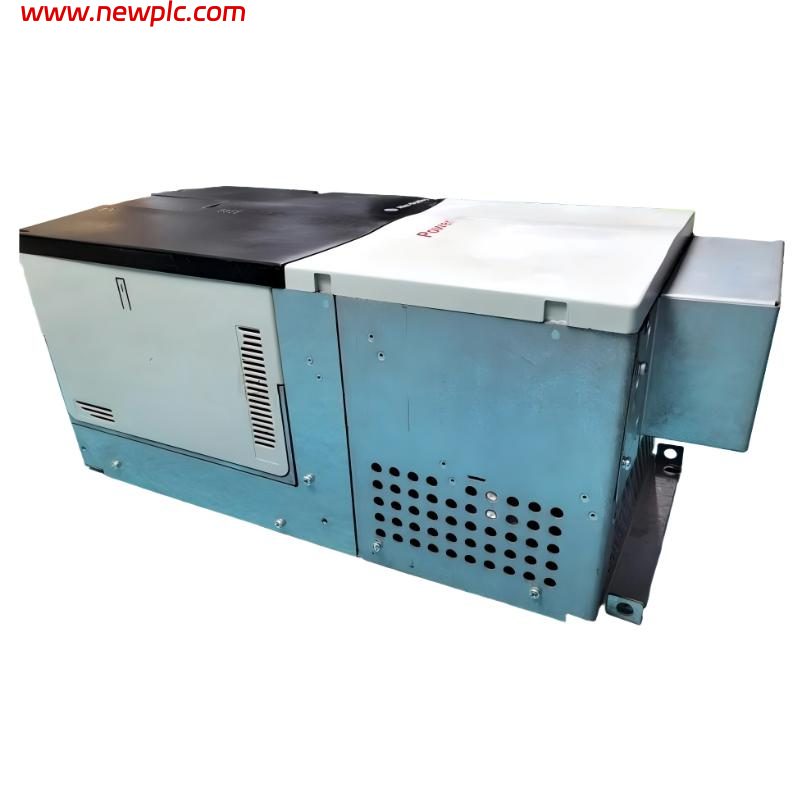
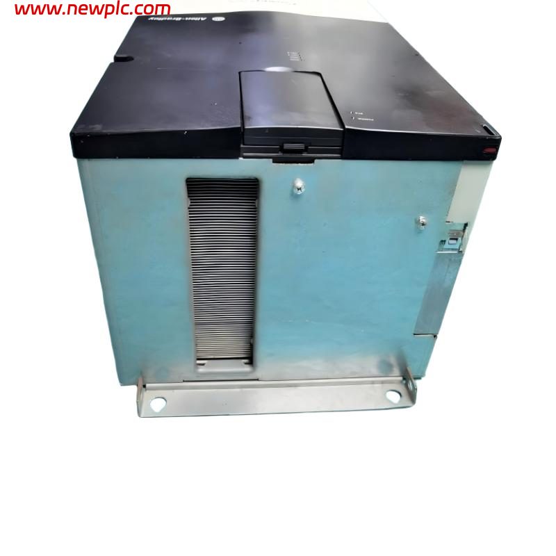
PowerFlex 700 AC Drive |
|
Input Voltage |
400 VAC |
|
Input Voltage Range |
380–480 VAC |
|
Input Phase |
3-phase |
|
Input Frequency |
50 Hz |
|
Rated Output Current |
205 A |
|
Normal-Duty Power Rating |
110 kW |
|
Heavy-Duty Power Rating |
90 kW |
|
Output Phase |
3-phase |
|
Output Voltage |
0 to rated motor voltage |
|
Maximum Output Frequency |
420 Hz |
|
Control Method |
Vector Control |
|
Control I/O |
24 V DC I/O |
|
Analog Inputs |
2 |
|
Analog Outputs |
2 |
|
Digital Inputs |
6 |
|
Digital Outputs |
3 |
|
Feedback |
No Feedback |
|
Communication Module |
EtherNet/IP DPI Module |
|
Human Interface Module |
LCD display with full numeric keypad and programming keys |
|
EMC Filter |
EMC filter with common-mode choke |
|
Brake IGBT |
Not included |
|
Internal Braking Resistor |
Not included |
|
Enclosure Rating |
IP20 / NEMA/UL Type 1 |
|
Frame Size |
Frame 6 |
|
PWM Frequency |
4 kHz at 400 VAC |
|
Efficiency |
Approximately 97.5% at rated current and nominal line voltage |
|
Displacement Power Factor |
Approximately 0.98 across the speed range |
|
Overload Capacity |
110% of rated current for up to 1 minute; 150% for up to 3 seconds |
|
Acceleration Time |
0–3600 s, programmable |
|
Deceleration Time |
0–3600 s, programmable |
|
Speed Regulation |
Approximately 0.1% of base speed in Vector Control without feedback |
|
Torque Regulation |
Approximately ±5% without feedback |
|
DC Bus Voltage |
Approximately 540 V DC at 380/400 VAC |
|
DC Bus Undervoltage Protection |
Approximately 305 V DC at 380/400 VAC |
|
DC Bus Overvoltage Protection |
Approximately 810 V DC at 380/400 VAC |
|
Maximum Altitude |
1000 m without derating |
|
Operating Temperature |
0–50 °C, depending on operating conditions |
|
Relative Humidity |
5–95%, non-condensing |
|
Short-Circuit Rating |
Up to 200,000 A symmetrical, depending on protection configuration |
|
Communication Protocol |
EtherNet/IP |
|
Motor Overload Protection |
Class 10 motor overload protection |
|
Stop Functions |
Coast, Ramp, DC Brake and programmable stopping functions |
|
Dimensions |
976.3 × 403.9 × 275.5 mm |
|
Weight |
71.44 kg |
|
Product Status |
Discontinued |
FAQ
FAQ
Q1: What applications are suitable for the Allen-Bradley 20BC205A3ANNAEC0?
A: The Allen-Bradley 20BC205A3ANNAEC0 is a high-power PowerFlex 700 AC Drive designed to control three-phase industrial motors. With a rated output current of 205 A, a normal-duty power rating of 110 kW, and a heavy-duty power rating of 90 kW, it is suitable for industrial machinery requiring controlled motor starting, stopping, speed regulation, and torque management.
Typical applications include conveyors, pumps, fans, material-handling systems, mechanical transmission equipment, and process machinery. Its Vector Control method supports improved motor response and speed regulation under changing loads. Before selecting the drive, evaluate the motor’s rated current, starting torque, load inertia, operating cycle, and overload requirements rather than relying on motor power alone.
Q2: What type of power supply does the 20BC205A3ANNAEC0 require?
A: The 20BC205A3ANNAEC0 is designed for a three-phase AC power supply in the 380–480 VAC range, with a nominal input voltage of 400 VAC and a listed input frequency of 50 Hz.
The installation requires a properly rated electrical distribution system, suitable circuit protection, disconnecting equipment, correctly sized power cables, and protective grounding. Because the drive has a rated output current of 205 A, the incoming power supply must be appropriate for the motor and expected operating load.
Before energizing the drive, verify the supply voltage, phase configuration, terminal connections, grounding, and protective devices. Ensure that incoming power is connected to the designated input terminals and that the motor wiring is connected to the correct output terminals. Installation and commissioning should be performed by qualified personnel.
Q3: What control functions are available on the 20BC205A3ANNAEC0?
A: The 20BC205A3ANNAEC0 uses Vector Control and provides 24 V DC control I/O, including two analog inputs, two analog outputs, six digital inputs, and three digital outputs. These interfaces support integration with external control equipment and allow the drive to respond to configured commands and operating references.
The drive supports programmable acceleration and deceleration times ranging from 0 to 3600 seconds. This flexibility helps accommodate different machine requirements, from relatively rapid speed changes to gradual acceleration and stopping for high-inertia loads.
For proper commissioning, enter the motor’s nameplate information accurately, including rated voltage, current, frequency, and speed as applicable. Incorrect motor parameters or unsuitable acceleration settings can contribute to excessive current, unstable operation, poor low-speed performance, or repeated protective trips.
Q4: Can the 20BC205A3ANNAEC0 operate without encoder feedback?
A: Yes. This configuration is specified as No Feedback, meaning it does not require a standard encoder for its normal motor-control configuration. Its Vector Control system estimates motor operating conditions using electrical measurements and internal control algorithms to regulate speed and torque.
Under appropriate operating conditions, the listed speed regulation is approximately 0.1% of base speed, with torque regulation of approximately ±5% without feedback. Actual performance depends on motor characteristics, parameter settings, load conditions, and commissioning quality.
This configuration can suit many conveyors, pumps, fans, and general-purpose industrial machines. However, applications requiring precision positioning, very low-speed performance, or tightly controlled closed-loop speed accuracy may need an encoder-based configuration. Confirm the application’s control requirements before choosing a no-feedback drive.
Q5: How should an overcurrent fault on the 20BC205A3ANNAEC0 be diagnosed?
A: An overcurrent fault may result from excessive mechanical load, motor wiring problems, incorrect motor parameters, or acceleration settings that demand too much current.
Begin by checking whether the driven machine is jammed or overloaded. Inspect bearings, gearboxes, couplings, conveyors, pumps, and other mechanical components for excessive friction or blockage. Next, examine the motor cables and connections for damaged insulation, loose terminals, phase-to-phase shorts, phase-to-ground faults, or incorrect wiring.
If the fault occurs primarily during acceleration, review the acceleration time. High-inertia loads may require a longer acceleration period to reduce current demand. Also verify the motor’s rated voltage, current, frequency, and speed settings. For Vector Control operation, check the motor-tuning procedure and relevant control parameters.
If the fault persists after external wiring, mechanical loading, and configuration have been checked, qualified technicians may need to inspect the drive’s power components and current-sensing circuitry. Isolate the power supply and follow the manufacturer’s safety procedures before inspecting electrical connections.
Q6: Why can the 20BC205A3ANNAEC0 trip on overvoltage during deceleration?
A: Overvoltage during deceleration commonly occurs when a motor returns regenerative energy to the drive’s DC bus. When a high-inertia load slows down rapidly, stored mechanical energy can raise the DC-bus voltage above the drive’s allowable limit, triggering an overvoltage fault.
The first step is to review the programmed deceleration time. Increasing this time can reduce the rate at which regenerative energy is returned to the DC bus. If the application requires frequent rapid stopping, however, a longer deceleration time may not be practical or sufficient.
This configuration does not include a built-in braking resistor or brake IGBT. Applications involving substantial regenerative energy should therefore be evaluated for a suitable external braking solution or another engineered method of handling regenerative energy. The selection should account for motor speed, load inertia, stopping frequency, and braking energy. Confirm hardware compatibility before adding braking components.
Q7: How can the 20BC205A3ANNAEC0 communicate with a PLC through EtherNet/IP?
A: The 20BC205A3ANNAEC0 is specified with an EtherNet/IP DPI communication configuration for integration with compatible PLCs and industrial control networks. Depending on the network configuration and PLC program, communication can support start and stop commands, speed references, drive status monitoring, fault reporting, and operating-data exchange.
During commissioning, configure the network addressing and communication parameters, verify the physical Ethernet connection, and ensure that the PLC program correctly maps the drive’s command, status, reference, and feedback data.
If the PLC detects the drive but cannot control it, check the drive’s selected command source, speed-reference source, command word, and PLC data mapping. If the drive cannot be detected, inspect the network connection, IP settings, addressing conflicts, communication hardware, and relevant configuration parameters.
Compatibility depends on the PLC, communication setup, and the exact drive configuration. Confirm the available documentation and required network settings before integrating the drive into an existing system.
Q8: What preventive maintenance is recommended for the 20BC205A3ANNAEC0?
A: Preventive maintenance should focus on cooling, electrical connections, environmental conditions, and communication reliability.
-
Cooling and ventilation: Keep airflow paths unobstructed and inspect the drive and electrical cabinet for dust, oil, moisture, and other contaminants. Check cooling components according to the operating environment.
-
Electrical connections: Inspect input, output, and grounding terminals for looseness, overheating, discoloration, corrosion, or insulation deterioration. Follow appropriate isolation and electrical-safety procedures before inspection.
-
Environmental conditions: Check that temperature, humidity, and installation conditions remain within the specified operating limits.
-
Communication network: Inspect EtherNet/IP cables and connectors for damage, loose connections, and intermittent communication problems.
-
Fault history: Review recurring overcurrent, overvoltage, undervoltage, and thermal faults. Investigate their underlying causes instead of repeatedly resetting the drive.
-
Operating performance: Monitor unusual motor noise, vibration, load changes, and repeated trips that may indicate mechanical or electrical problems.
Tags
Packing & Delivery
We will use wear-resistant cartons to seal the boxes, and take photos for your confirmation before sealing. We will pack the boxes only after confirmation.
For express delivery, we will use DHL, UPS, TNT, FedEx and EMS.
Please rest assured that we have a deep cooperation with express delivery companies and can ensure that your goods are delivered to you in good condition.

